How it works
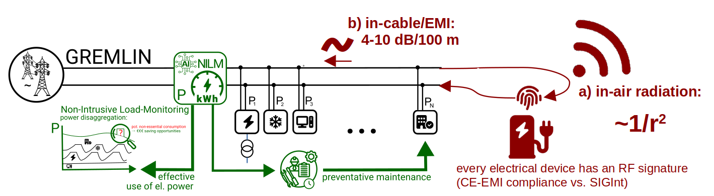
All switching electrical devices — switch-mode power supplies, motor drives, LED drivers, magnet power converters, RF amplifiers, etc. — emit characteristic electromagnetic-interference (EMI) signatures: switching frequencies, harmonics, transients, and others that depend on the device type and its operating state, and form its characteristic 'RF fingerprint'. These signatures are unique enough per device (even between identical designs) to identify and disaggregate the contributions of individual devices on a shared mains feed.
Every real switching device leaves a residual emission on the mains even when it is fully compliant with EMC/EMI norms — those norms bound the level but cannot suppress the residual entirely. This unavoidable residual is what GREMLIN uses. See EMI signatures and compliance for the conducted-versus-radiated physics, the unavoidable-residual argument, and the brief note on the same observation's security-side lineage (TEMPEST, van Eck).
Single-point disaggregation and NILM
GREMLIN's measurement sits at an upstream mains feed, reading the conducted channel — emissions travel along the facility's own power wiring with low attenuation (a few dB per hundred metres), whereas radiated emissions fall off rapidly with distance (≈ 1/r²) and would demand sensors near every device. The wiring acts as a passive collection network: one high-bandwidth measurement at a feed point sees the superposition of many devices' signatures at once.
Since each device's fingerprint is distinct, the superposition can be disaggregated back into per-device contributions. GREMLIN couples this single-point sensing with non-intrusive load monitoring (NILM) and a learned classifier — one cost-effective, robust, high-bandwidth acquisition point instead of instrumenting thousands of individual devices, each with its own calibration, reliability and maintenance burden.
 |
 |
 |
 |
 |
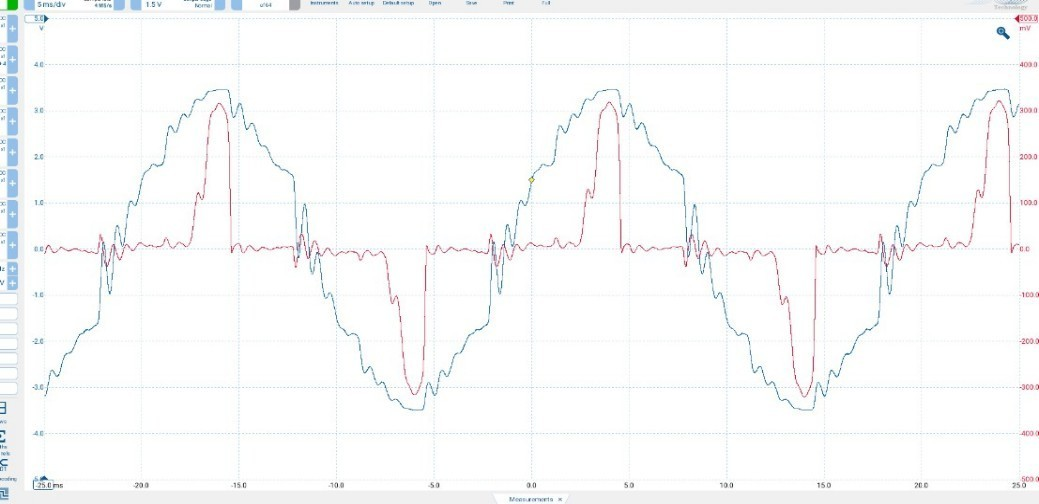 |
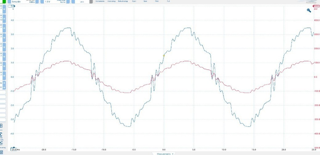
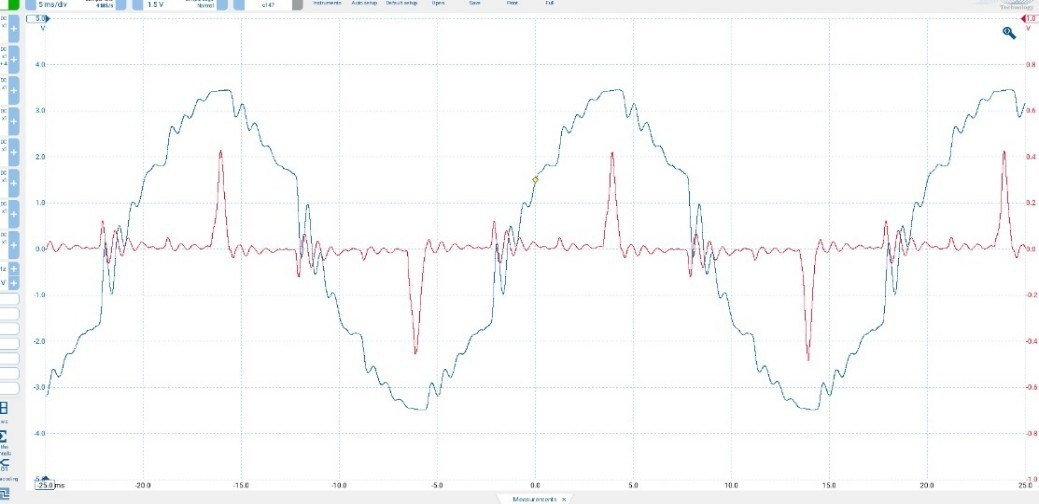
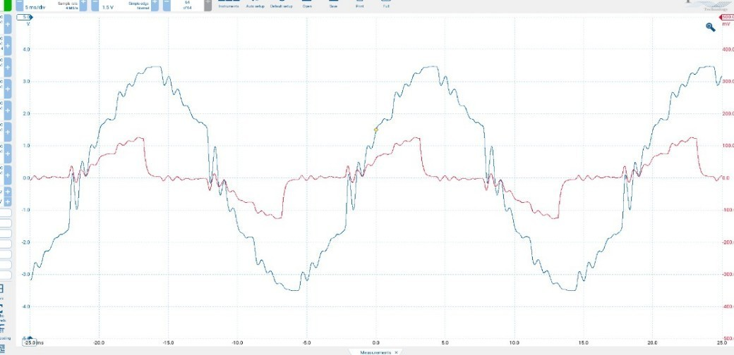
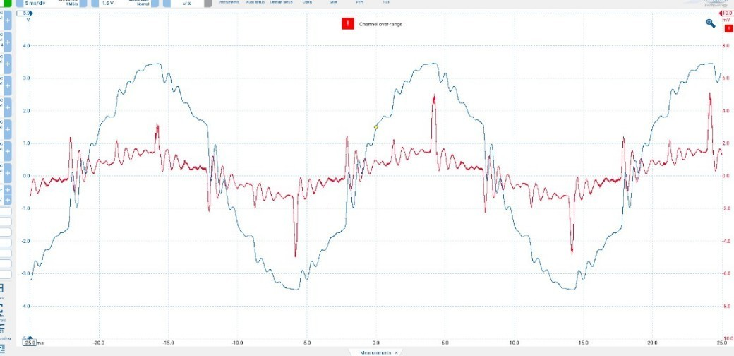
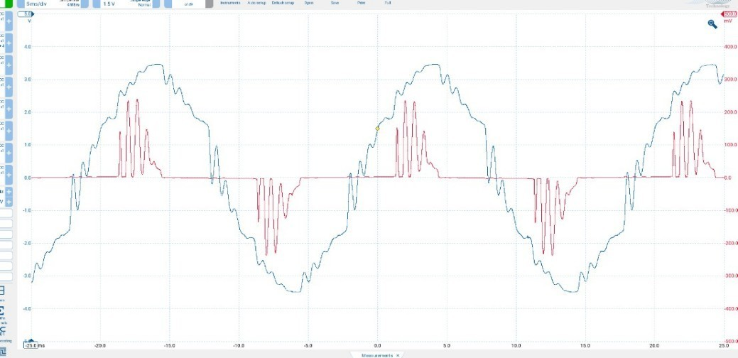
Example device signatures in the time domain (voltage / current), with and without load. The differences between devices and operating states are what make single-point disaggregation possible.
"If you can see it, there's a good chance a machine can be taught to detect and classify it."
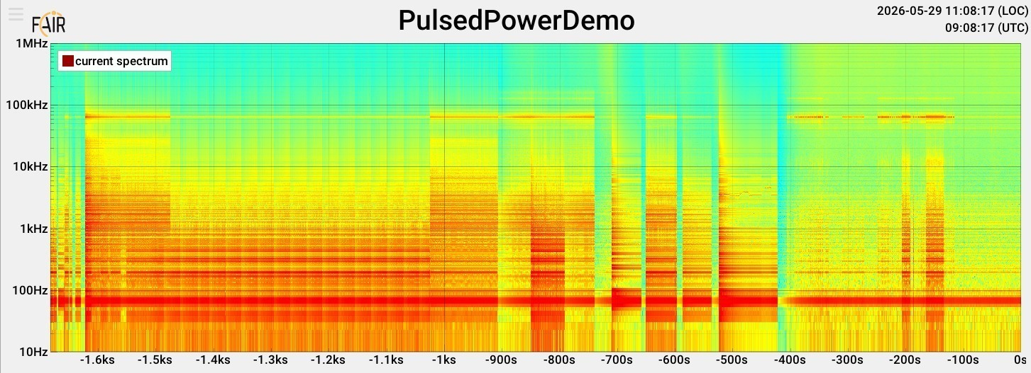
The same activity is equally visible in the frequency domain over time:
Ageing as RF Signature
The same conducted-EMI signal carries information about how each device is ageing. As power-electronic components age — capacitor electrolytes evaporating, IGBT die-attach voiding, gate-oxide drift — the device's switching waveform changes shape, and the spectral content it conducts onto the mains shifts with it. Trained on each device's healthy signature, GREMLIN's classifier can detect that drift well before any conventional electrical-protection alarm fires.
A result that most directly applies is - for example -- that of Dimech and Dawson (2024), who subjected ten 600 V / 16 A IGBTs to accelerated thermo-electrical ageing and measured each device's conducted-EMI before and after. The aggregated peak-spectral-power below shows a systematic decrease in the high-frequency content of the conducted emission as the devices age: the slowed turn-off transient (longer tail current after die-attach voiding) carries less Fourier weight at the upper end of the band. The same drift would show up at a facility's feed point integrated across many devices.
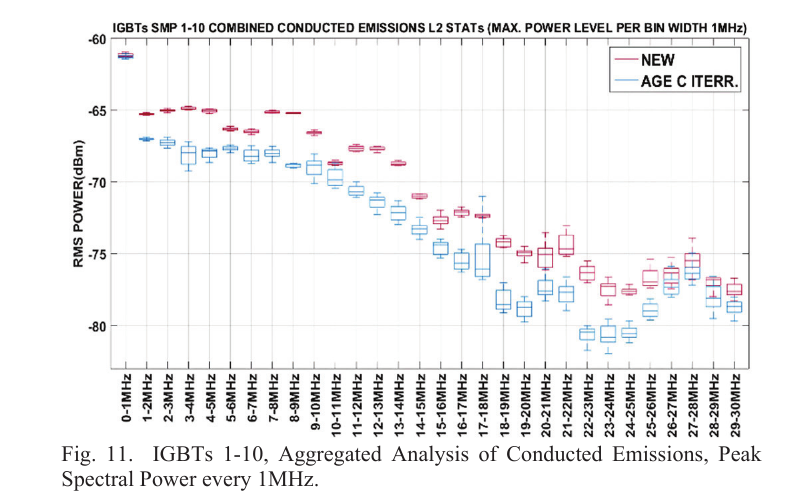
Aggregated peak spectral power of the conducted-EMI emissions before (NEW) and after three iterations of accelerated thermo-electrical ageing (AGE C ITER), across ten 600 V / 16 A IGBTs in 1 MHz bins. Reproduced from Dimech and Dawson (2024), Fig. 11. © 2024 IEEE, used under scientific fair-use with attribution.
Benchmarked against Classic Methods
The learned model is benchmarked against established classical methods — for example TSpectrum, NAFF, and CLEAN — against controlled ground truth: known switching events, known device states, and instrumented circuits. Results can therefore be cross-checked against well-understood baselines rather than taken on trust. Reported metrics include detection rate, false positives / negatives, clustering quality, power-estimation error, and ageing / anomaly lead time.
Real-World Setup and Testing Conditions
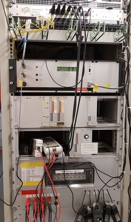
Validation uses real facility infrastructure — for example GSI/FAIR's instrumented mains feed point on the primary (input) side and instrumentation around the SIS18 and ESR main dipole and quadrupole circuits on the secondary (load) side. This enables the possibility to evaluate various control-theory level methods against real-world operating conditions, not only on bench-tests:
 |
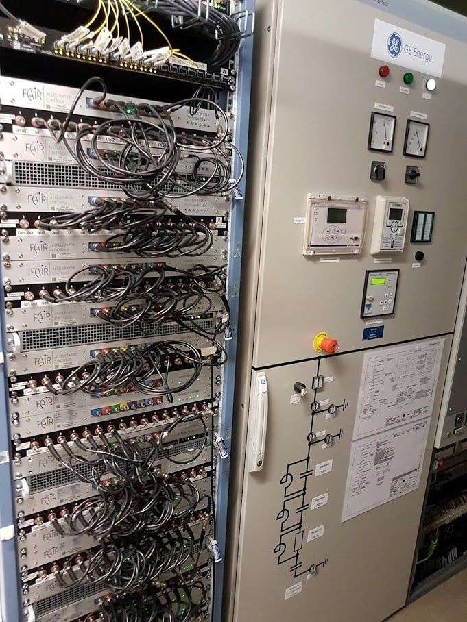 |
Left: primary-side (mains-feed) measurement point — what GREMLIN sees in deployment. Right: secondary-side (load) instrumentation on the SIS18 / ESR main dipole and quadrupole power-converter circuits — the independent ground truth used to benchmark the disaggregation chain and the ageing-drift detection.
This pairing is deliberate: GREMLIN's operational output is nominally read from the conducted EMI that reflects back to the mains feed — the upstream observable, available without per-device sensors. In combination with the additionally instrumented power converter on the secondary load side, the actual electrical converter efficiency can be independently used as a ground truth reference for validation.
Complementary, a known excitation/power cycle on the secondary side can be propagated forward through the network and compared, sample-for-sample, against the primary-side observable; the inverse problem — disaggregating the primary-side signal back into per-converter contributions — can in turn be checked against the secondary-side ground truth. Most NILM efforts at home or building scale rely on the mains-side measurement alone with crude on/off device labels; simultaneous high-bandwidth access to both sides of the transfer function at facility scale is a distinguishing feature of this work, and is the main reason its benchmarking can be done quantitatively rather than asserted.
Because the measurement is non-intrusive, it can also run during shutdowns, maintenance windows, and commissioning gaps — periods when the secondary-side load pattern is well-controlled and ideal for system identification.