EMI signatures and compliance
Switching power-electronic devices — switch-mode power supplies, motor drives, magnet power converters, RF amplifiers, LED drivers — generate characteristic electromagnetic-interference (EMI) signatures. The fundamental components of these signatures are the device's switching frequency (typically tens to hundreds of kHz and up to well into the MHz range), its harmonics, and the switching transients themselves, each of which depends on the device's design and its instantaneous operating state.
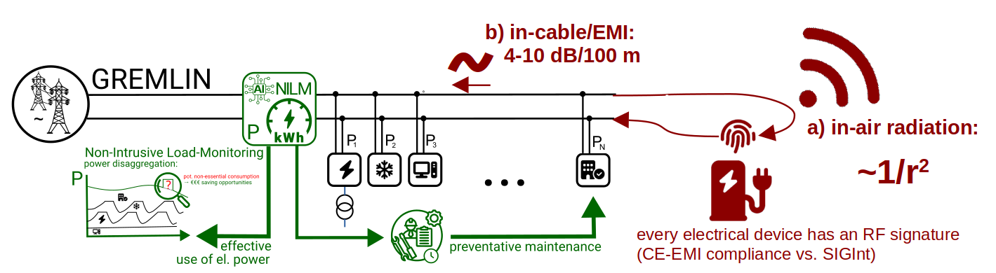
The work described on this site exploits these signatures constructively, reading them at a small number of upstream measurement points in order to (i) identify which devices are currently drawing power, (ii) track the temporal evolution of each device's signature, and (iii) identify unaccounted for devices. Two physical facts underpin the feasibility of the approach at facility scale: the propagation behaviour of conducted EMI on shared mains wiring, and the unavoidable nature of the residual emissions that real switching equipment leaves on those mains under all operating conditions.
1. The unavoidable residual in EMC-compliant equipment
Power-electronic devices placed on the regulated market are required to keep their conducted and radiated emissions below internationally agreed limits prior to release. In practice those emissions are bounded by filtering and engineering, but cannot be entirely suppressed. Short of operating exclusively from battery sources, every switching power converter, motor drive, and switch-mode supply leaves a residual disturbance on its shared mains feed that carries:
- the device's fundamental switching frequency and its harmonics;
- the spectral signatures of any sub-harmonic or quasi-periodic modulations caused by the switching;
- the time evolution of those features as the device transitions between operating states.
The work described here reads this unavoidable residual: the characteristic fingerprint that each device cannot help imprinting on the wiring, irrespective of its compliance margin. The fact that the residual is bounded by construction (no compliant device dominates the network) and that it differs across devices (each design and operating state has its own spectral content) is precisely what makes single-point disaggregation tractable.
In the European Union these limits are the harmonised standards behind the EMC Directive (2014/30/EU) and resulting CE marking: for industrial, scientific and medical (ISM) equipment the governing standard is EN 55011 (or: CISPR 11). Similarly FCC Part 15 and MIL-STD-461 (method CE102) are used in the United States. Each caps the mains-terminal disturbance voltage a device may inject back onto its supply over roughly 150 kHz – 30 MHz, split by operating environment (Class A industrial versus Class B residential).
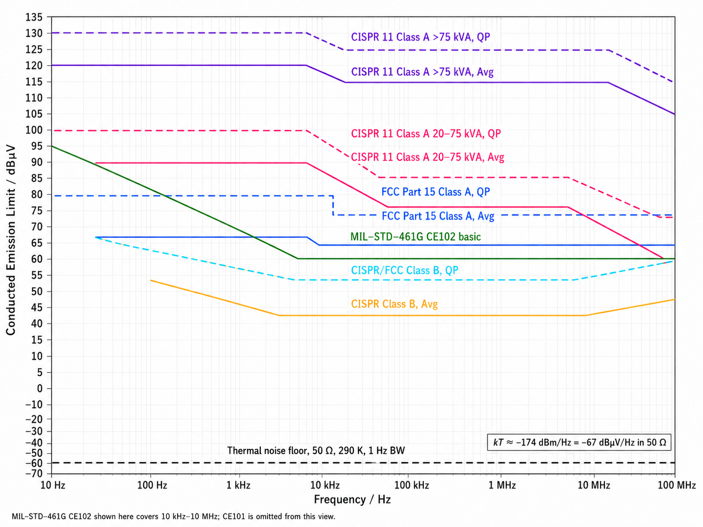
Indicative conducted-emission limit envelopes (mains-terminal disturbance voltage, dBµV) across the common regimes. Whatever limit applies, it bounds the residual emission — it does not remove it; GREMLIN reads precisely what remains underneath and above the thermal noise floor limit.
2. Conducted versus radiated propagation
Emissions from a device reach a remote observer through two physically distinct propagation channels.
-
Conducted EMI propagates along the facility's own mains wiring with low attenuation — typically of order a few dB per hundred metres of cable (broadly 4 – 10 dB per 100 m, depending on cable-type, electrical loading, and frequency). A signature injected by a device located deep within the plant therefore remains detectable at a shared upstream feed point. Also, the location of the device in the network topology can be partially recovered from the time-domain signature.
-
Radiated emissions fall off rapidly with distance, broadly as 1/r² in the near-to-far-field regime. A radiated approach is intrinsically local, would demand sensors near every device of interest, or targeted long-distance over-the-air monitoring.
The contrast — slow, near-linear-in-dB conducted loss versus inverse-square radiated loss — is what makes single-point sensing viable. The wiring acts as a passive collection network: one high-bandwidth measurement at a feed point captures the superposition of many devices' conducted signatures simultaneously, and that superposition is the input to disaggregation. Conducted EMI at upstream mains feed points is therefore the primary observable. Radiated emissions remain a possible complement where they are usefully accessible — for example, in cabinet-internal or near-equipment sensing — but they are not the primary measurement channel this project want to follow-up on.
3. Historical Lineage of EMI-signature observation
The proposition that every electrical device emits a characteristic electromagnetic signature is not novel. Its experimental foundation was laid by Heinrich Hertz (1887–1888), whose spark-gap experiments at Karlsruhe first generated and detected electromagnetic waves at a distance, providing the experimental confirmation of Maxwell's equations. The civilian descendants of that demonstration are pivotal: Nikola Tesla's and later Marconi's wireless telegraphy of the 1890s evolved into broadcast radio and the modern wireless-communications stack; power-line communication (PLC) has carried utility SCADA telemetry over the mains since the 1920s, and underlies present-day consumer mains-networking standards. The shared physical premise of all of these is the one this site rests on: conductors carry useful, separable information at frequencies far higher than their fundamental 50 / 60 Hz, and those signals propagate over operationally useful distances.
A related branch of the same physics is the device-specific signature literature, which became visible in 1943 when Bell Labs engineers observed — incidentally, while testing a wartime cipher mixer — that a device's internal logical state could be reconstructed from voltage spikes leaking onto distant laboratory oscilloscopes (NSA, 1972; declassified 2007). The phenomenon entered the open scientific literature when van Eck (1985) demonstrated that a CRT video image could be reconstructed at distance using a modified television receiver, and was subsequently placed on a rigorous experimental footing by Kuhn (2003). In the security community, the cluster of work that grew from the 1943 observation has continued under the codename TEMPEST.
The constructive question posed on the same physics here is: what does the residual emission of a switching device tell the operator about which device is presently running and how its electrical health is evolving over time? The answer, restricted to energy accounting and preventative maintenance, is the subject of What it provides and the Ageing as signature summary on the How it works page.
4. Scope and intended use
The system described on this site is, by construction, a diagnostic layer. Its scope is restricted to energy accounting and maintenance scheduling, computed from device-aggregate signatures observed at a facility's own mains feed points. It does not target signals carrying user content, does not infer information about individuals, and does not actuate or regulate any load. Where the analysis surfaces an unaccounted-for load — power drawn on the network that does not match a known signature — the disclosed fact is solely that something is consuming power matching no known fingerprint, not what that something is doing internally. Acting on any output of the system remains a human and planning decision.